In order to improve the mechanical properties (especially the stiffness) of a part, glass fibers are often added to thermoplastic polymers. However, the thermo- mechanical material properties of the created compound are anisotropic (direction dependent). Due to the shear flow during injection, the local alignment of the fibers corresponds to a three dimensional flow situation, which results in a three dimensional distribution of the fibers.
The local dependency of part properties becomes a challenge for calculation engineers. The availability and reliability of thermo-mechanical material data is necessary to properly evaluate static-load situations, fatigue behavior and life-time prediction. If isotropic values are used, the best scenario would be that the parts would be over dimensioned. In the worst scenario, parts would fail.
SIGMASOFT® Virtual Molding simulates the local three dimensional fiber orientation, following the flow situation during the injection and packing phase in three dimensions as well. A suitable micromechanical modeling determines the local thermo-mechanical properties of the injection molded component based on the temperature and pressure history of the polymer, as well as on the fiber orientation. This data cannot only be used for the internal shrinkage and warpage calculation in SIGMASOFT®, but also for the mapping with the SIGMALink module, where these results can simply be transferred to FE meshes (shells and solids), e.g. for Abaqus, Ansys, Marc, Radios or other structural simulation software. Having this in mind, the calculation engineer is now able to use the real local anisotropic component properties for his evaluations.
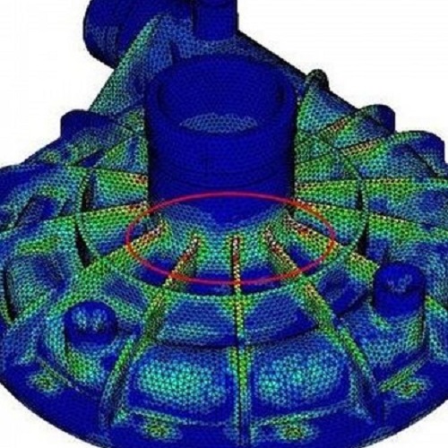
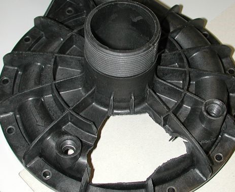
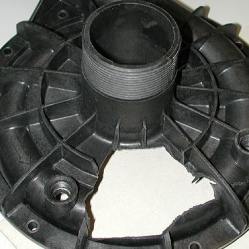
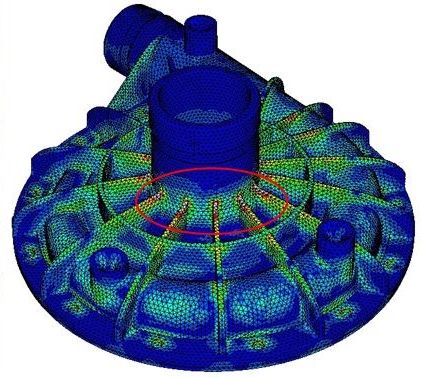
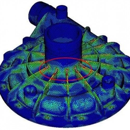
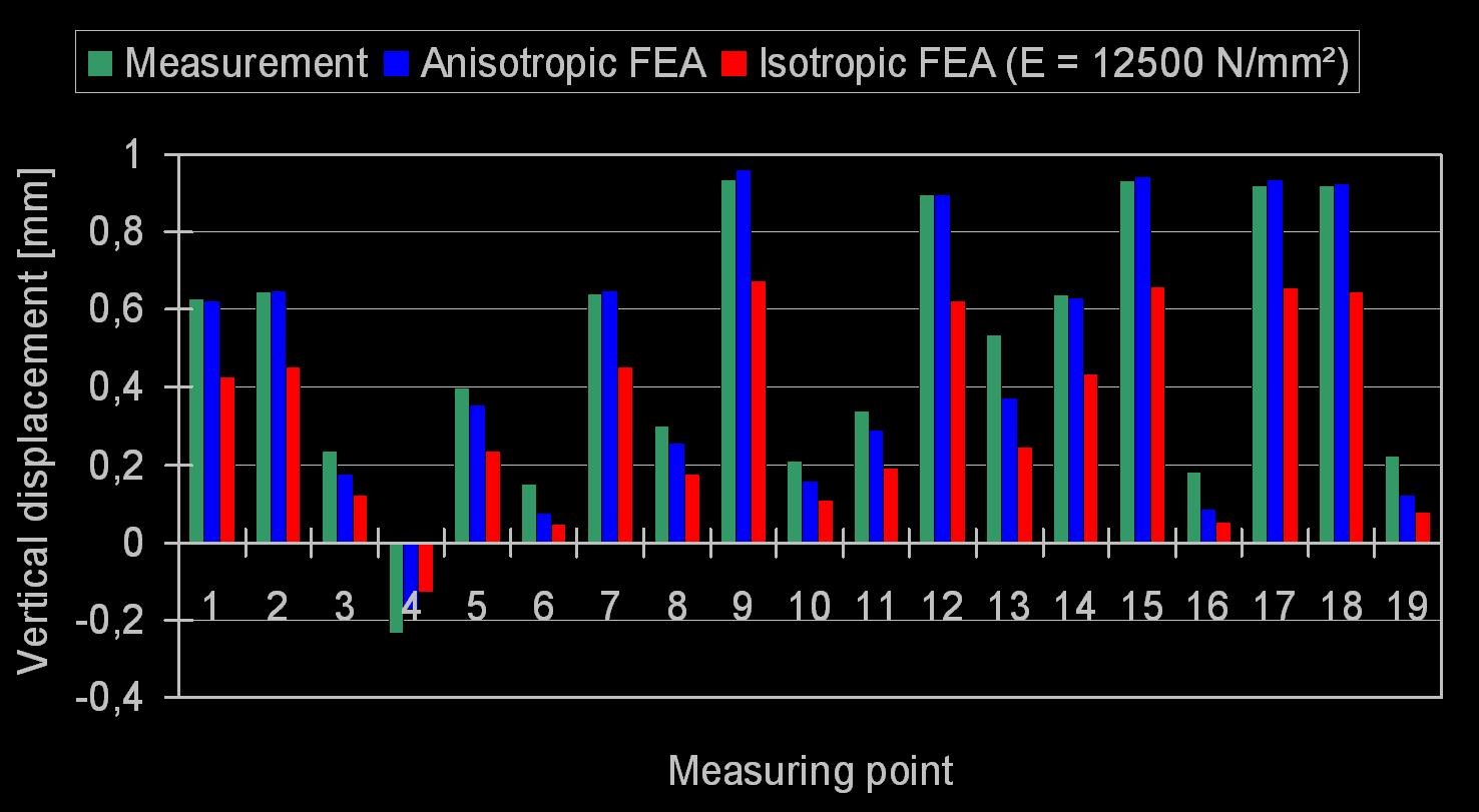
A housing component made of PA GF50, as depicted in Figure 1, experiences deformation caused by an internal pressure test at room temperature. Experimental results tracked with an optical measuring system deliver the green measured values for the vertical displacement (Figure 3). Theoretical results obtained with an FE simulation using simplified isotropic substitution values return the values shown in the red columns.
It can be seen that the isotropic calculation returns a qualitatively accurate deformation image. But it significantly underestimates the deformation from the quantitative point of view – by a factor of 2. The recalculation of the loading case – using the fiber orientation state simulated with SIGMASOFT®, as well as the resulting local anisotropic stiffness values for the structure simulation, have led to the results shown in the blue columns. The anisotropic structure calculation shows a deformation image with quantitatively high accuracy, giving the basis for an efficient and secure component design.
Besides increasing the reliability of the mechanical analysis, including the anisotropic part behavior in the mechanical analysis can improve the understanding of the part deformation and therefore increase the competence of the design team. As the accuracy of the analysis is increased, unnecessary over dimensioning can be avoided, thus reducing the material consumption.
