Potholder optimized for LSR injection molding
Potholder optimized for LSR injection molding
Resource-efficient benchmarking of injection concepts through virtual optimization
The flow behavior of polymer materials in a cavity depends on numerous factors, and therefore is difficult to predict. Modern simulation technologies support mold and process design by calculating and comparing different injection concepts and ranking them by selected criteria. In this approach, no material resources are wasted while the required effort and time remain minimal. In the case of a highly complex LSR part, mold design and injection concept were optimized upfront, so high-quality parts were successfully produced in the first acceptance run.
RFP 3/2020 - Volume 15, pages 120-123
The polymer flow in an injection mold depends on various factors, in particular, the material properties and process settings. With experience, practical knowledge and sometimes even intuition, most skilled mold makers succeed in designing a mold producing acceptable parts in the first production run. However, the increased complexity of the part decreases the probability of first run success. As a result, the projects often run through cycles of upgrades with modifications to the mold steel or changes to the injection system requiring modifications of the mold or cold runner deck. Nowadays, mold makers and process engineers can analyze the injection molding process upfront by means of simulation, saving time, man hours and material, required to finetune the process [1].
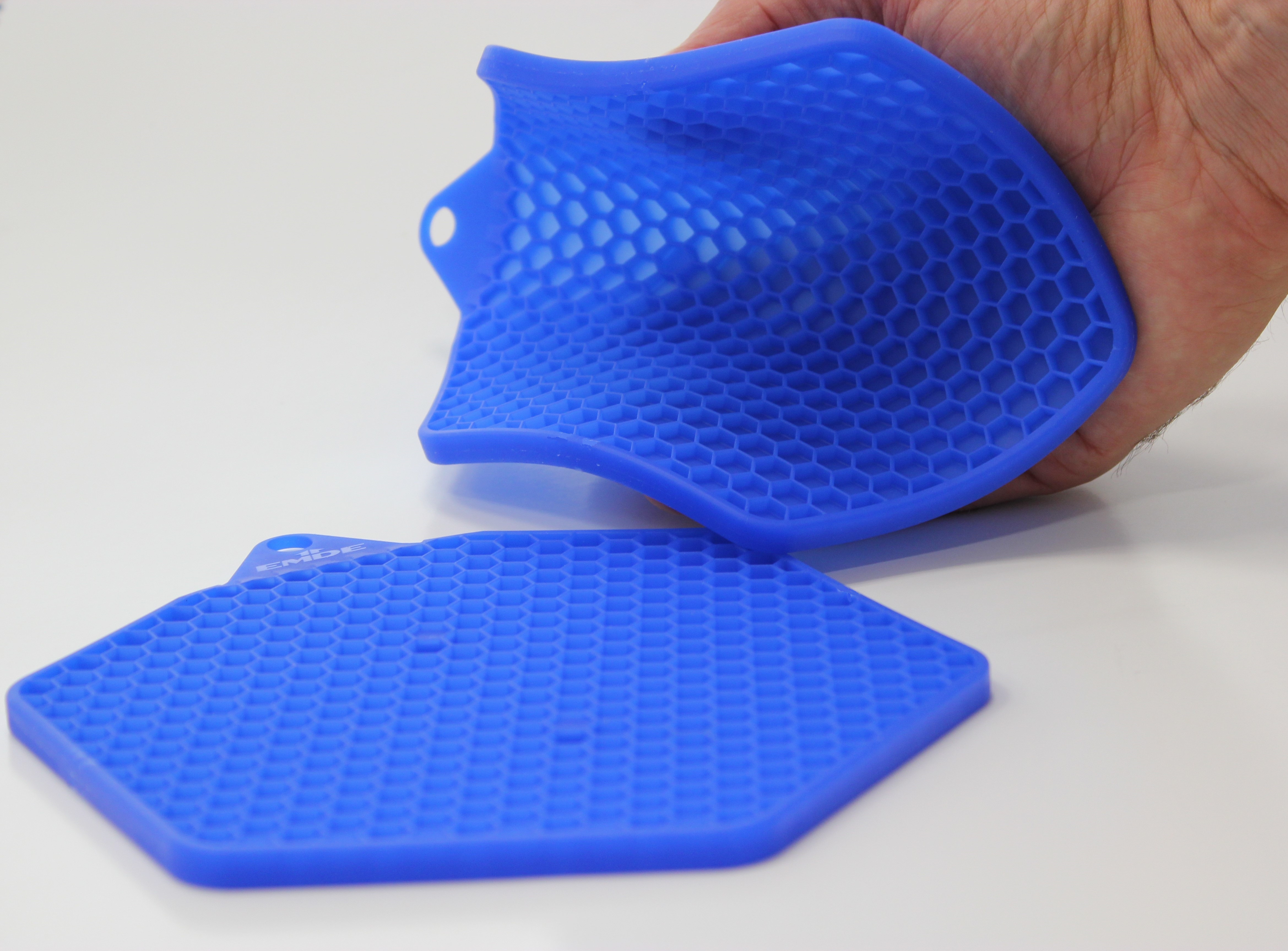
An example for a complex article is a pot-holder (fig. 1) with an unusual shape and a wall thickness of just 1 mm in its entire honeycomb structure made from liquid silicone rubber (LSR). The concept was a joint industry project for K 2019 and exhibited in full production. Financial and timeline constraints made physical prototyping impossible, therefore the feasibility study as well as design validations for part, cold runner, mold and process were carried out virtually.
„This is only a potholder“ – but, as often in life, the devil is in the details. The part looks really simple, apart from the ornate honeycomb structure. Millions are manufactured in Far East in compression molding based on Silicone HCR. But there was no known reference or experience with similar parts in LSR injection molding. The required injection pressure to fill the huge thin-walled honeycomb area as well as the best position to gate the part were unknown.
While the part looks symmetrical, it is not: the distance between center to the horizontal side wall is significantly shorter than to the vertical. The thick-walled ring surrounding the thin-walled center area can lead to interesting surprises when filling the part. There the flow front is much faster, mak- ing air entrapments practically unavoidable. The first and natural thought of the designers – using a central gate – wouldn’t have worked, we will elaborate on this point later in this article.
From design to molded part
During the designing phase, the focus was on the part geometry only. The position of the injection gate(s) is of critical importance. It fixes the length of the longest flow path and determines if the cavity is filled 100 % under influence of curing kinetics and rheology. It is also critical for the injection pressure and therefore impacts the choice regarding the best molding machine to be used. In this project example, mold and machine had to be ordered simultaneously and the smallest technically possible machine was desired. The key question was whether clamping force and injection pressure were sufficient. The venting of the cavity had to be at spots that were easily accessible to prevent optical failures through air entrapments. After fulfilling all these requirements and completely filling the cavity, the next open questions were curing and cycle time. Ideally, the entire part should crosslink evenly and completely. Areas which, based on flow history or wall thickness, cure later impose the required cure and cycle time.
Often a prototype mold is built to prove the developed concept. This consumes resources while the purpose is mainly manufacturing of test pieces to evaluate the concept. In case of success, preseries prototypes are molded before the mass production mold is constructed. An alternative route is using simulation for process design and testing of different approaches. Doing so, the company saves resources, implementing the entire manufacturing study virtually. This can be advantageous, especially if schedules are tight, because when doing this virtually several concepts or settings can be checked simultaneously. In regard to this potholder project, the tight schedule was the deciding factor causing the project partners to simulate the entire manufacturing process of mold, cold runner and machine. By using SIGMASOFT Virtual Molding they were able to virtually analyze and optimize the entire process.
Optimal filling of the cavity
To determine, how a shape like the complex potholder is filled with LSR, it is a good approach to imagine the flow path of the polymer and consider how the material properties are changing during the filling:
- The cold material passes the machine nozzle and cold runner deck at room temperature before reaching the heated cavity.
- When reaching the cavity, the temperature steeply increases due to mold temperature and shear
- Temperature initiates the curing process of The heat transfer depends on temperature gradient, heat conductivity and on time.
- Therefore, the flow path has to be completed in a filling time within the curing kinetics of the
- Fast filling e.g. results in higher temperatures which may start the curing process too
- This results in filling speeds and pressures which have to be within the machine capabilities.
- The filling pressure on the other hand depends on the rheological material properties – which are again depending on temperature, shear and state of cure.
Based on the above variety of points to consider, only a few of the easier filling concepts can be thought through or discussed with other processing experts. In most cases, this is not enough to include all aspects and process details to find the optimal combination.
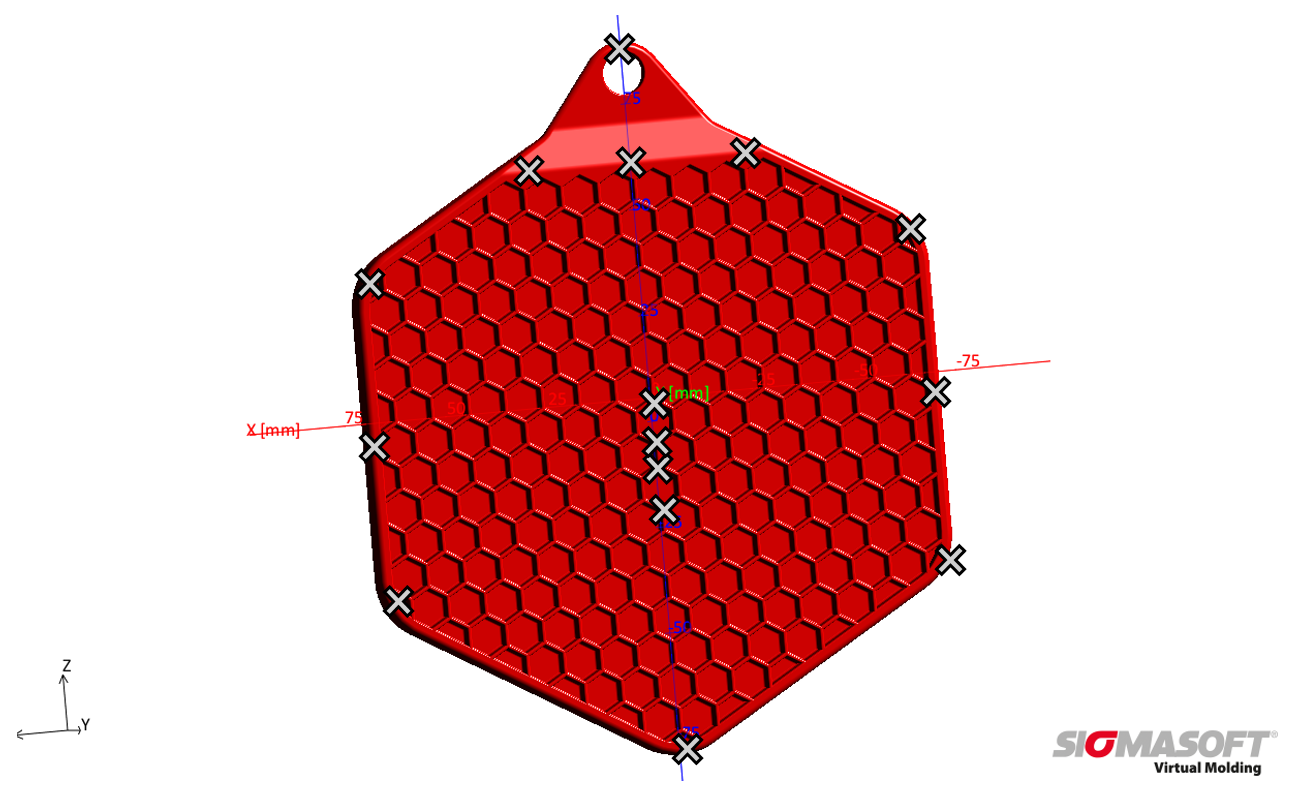
The solution is available through modern approaches of injection molding simulation which go beyond basic calculation of cavity filling. The software Sigmasoft Virtual Molding offers the possibility to compare and benchmark several combinations of geometries and process parameters with minimal effort, based on modern optimiza- tion algorithms. In the first design phase, the potholder was subject of a virtual Design of Experiments (DoE). The filling of the cavity was calculated based on 15 different single and double cold runner nozzles onto the part (fig. 2) using two filling times and two different temperatures. Afterward, the results were compared for criteria like flow length and required injection pressure.
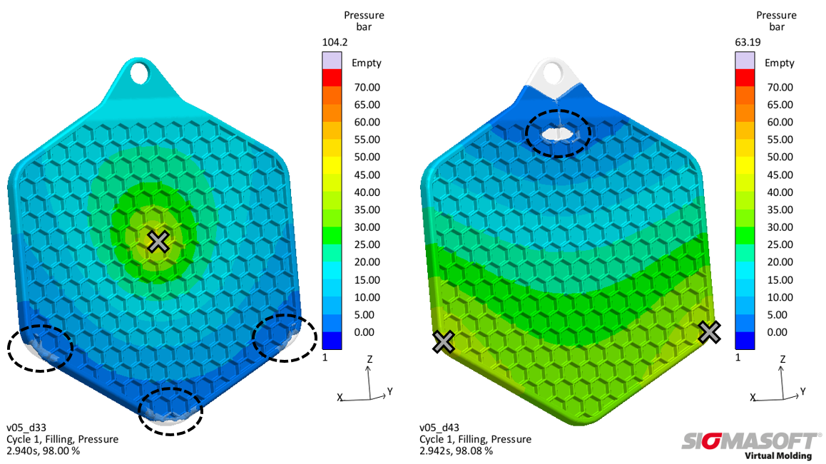
After benchmarking a total of 60 combinations, the decision was made to gate the part in the center. This led to a flow length of 100 mm at an injection pressure of 100 bar. This pressure is not the lowest of the variants but has clear advantages with focus on the filling pattern. Figure 3 compares filling behavior and required pressure of this design with an alternative setup. The version with a lower filling pressure (right) has the risk of air entrapment in the center of the part, while central injection drives the air to the sidewall of the geometry, where venting is much easier.
The disadvantage of central gating was the exact position of the junction points. Depending on process parameters and material selection (viscosity) their location could vary (in some cases even towards the inside of the surface area). This means some risk to a robust and fully automated manufacturing process. It is important to know, that the shear thinning LSR has a very low viscosity during filling. Therefore, the parting line of the mold must close tightly with a maximum tolerance of 5 µm (too small for effective venting), otherwise, the LSR will flow through the clearance gap and creates flash. The exact knowledge of the junction points enables additional measures e.g. microgrinded areas or needle gate nozzles for local venting. The part should always be demolded trim-free.
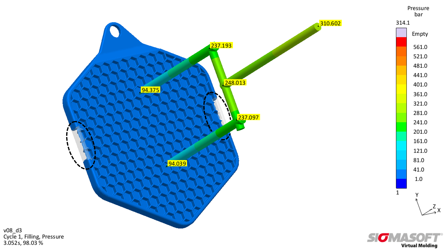
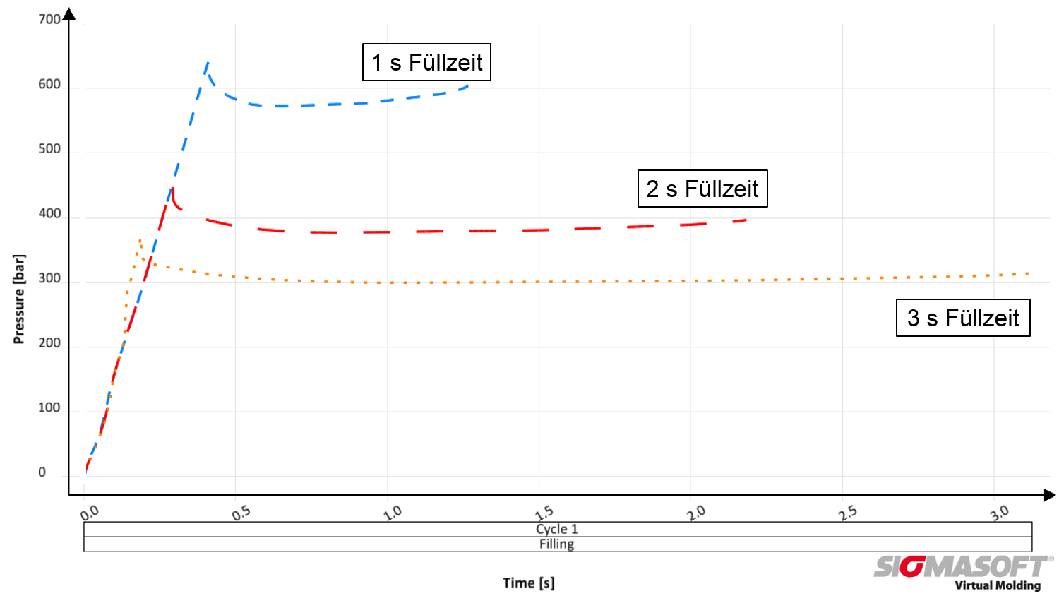
When discussing how the complex honeycomb structure can be filled with the approx. 85 g of LSR in an acceptable filling time without requiring high filling pressure, the team chose to develop a cold runner concept with two nozzles. This provided the additional benefit to reduce the number of junction points to only two and their location was always fixed, independent of process or material variations. The cold runner showed to consume 220 bar, approx. 70 % of the total injection pressure of 315 bar at a filling time of 3 s (fig. 4). The charts of the required pressures for filling times of 1 s and 2 s were also computed and compared (fig. 5). A faster filling with only 1 s time required a maximum pressure of approx. 650 bar, which is safely within the capability of the selected smaller molding machine.
Last fine tuning of the design
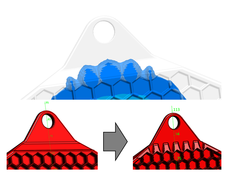
Another detail that became apparent, when analyzing the simulations, was the area where the material flows over into the hanger area (fig. 6, top). When the low viscosity LSR flows from the honeycomb area with 1 mm wall thickness into the thicker hanger area (3 mm), jetting occurs, which can potentially cause air entrapments. These air entrapments increase the likelihood of optical failures as well as internal holes in this function critical area. To avoid jetting, the geometry was modified accordingly (fig. 6, bottom).
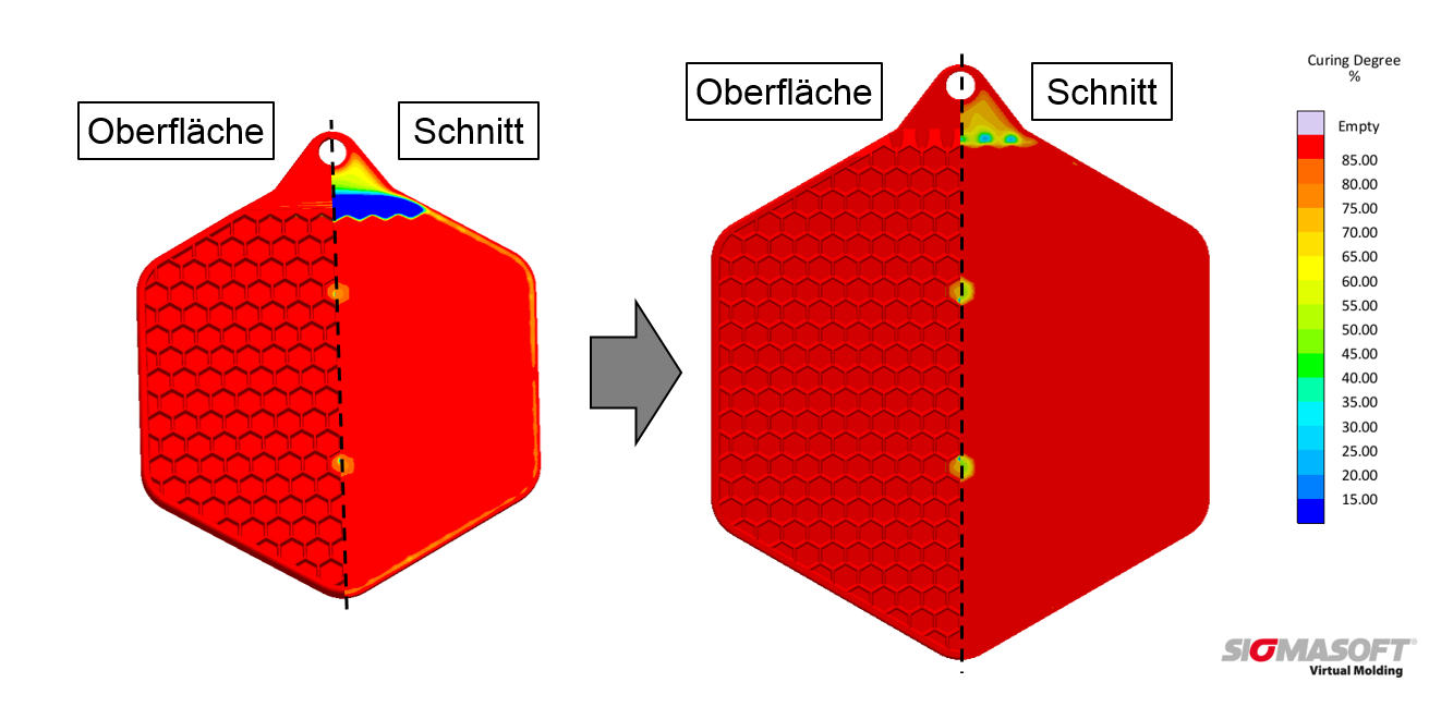
But the improvement of flow in the hanger area was not the only reason for the design update. It also contributed to shortening the cycle time because the high wall thickness hanger area was crosslinking later, prolonging the cycle unnecessarily. This becomes visible, when reviewing the degree of cure on the surface and in the section of the part at a cure time of 25 s at 170 °C. The hanger shows only little curing progress inside while the surface seems to be cured completely (fig. 7, left). It requires an additional 15 s cycle time for stable demolding. The modified geometry of the hanger exhibits a much faster progress of curing at the same time and temperature conditions (fig. 7, right). As a result, the curing time does not depend on the hanger anymore but on the thicker honeycombs where the two injection nozzles are diving into the mold platen. A final increase of the mold temperature by 10 °C resulted in sufficient curing of the entire potholder within 25 s allowing dimensionally stable demolding.
In the next step, the size of the potholder was enlarged. Because the simulations showed that the required filling pressure and clamping force were far below the machine limits, the total part size was increased for better usability (fig. 7, left and right). Final simulations and the real process showed the fitting pressure requirement at 3 s filling time to be slightly above 500 bar.
The fully automated manufacturing cell was operated during the whole K 2019 trade fair using the evaluated process parameters of injection time, temperature and curing time. Some thousand potholders were handed over to the interested visitors directly from the machine for their home use.
Summary
An ideal gating concept for the potholder was developed the with help of virtual DoE and finally implemented in a two-nozzle cold runner to optimize part filling. To ensure the machine capabilities fit the pressure requirements different filling concepts and times were calculated. The optimization of the geometry prevented the formation of air entrapments and avoided longer cycle times. It was ensured that good parts were manufactured already in the first processing trials. With the help of simulation, such fundamental feasibility analyses are becoming increasingly resourceefficient and, in simplified form, are often already in use for part calculations in the offer phase.
References
[1] Implementing complex LSR molding from a white piece of paper, Vanessa Frekers, B.Sc., Sigma Engineering GmbH, presentation at Rubber meets Science, IKV Aachen, June 2019.

