Determining the Optimum Heating Concept for BMC
Determining the Optimum Heating Concept for BMC
Simple Answers to Complex Questions in Mold Design: To be able to cost efficiently design complex molds, e.g. for BMC components, it is essential to take into account the mold cooling. Thus the mold costs increase in a linear relationship with the number of heating cartridges provided. It is therefore desirable to aim for as few cartridges as possible, but at the same time, this can have a disadvantageous effect on the homogeneity of the temperature distribution and the robustness of the process. Until now, these conflicting goals were largely resolved based on experience. But it can also be done systematically.
Authors: Vanessa Schwittay, Diogo Alves de Sá
First published in Kunststoffe international 12/2017, page 30-33
Process simulation is often used nowadays to confirm planned mold concepts; however, a methodical way of finding the optimum and cost-effective solution is not generally available. Conventional approaches to simulation shift the iterations from the mold and machine back to the computer, and are therefore significantly more economical. However, the result still depends on the user’s experience. It is therefore still not clear whether the potential of the mold and process is completely exploited.
New approaches to simulation, such as virtual design of experiments (DoE) together with automated optimization use a reverse approach. By specifying the desired result, e.g. cycle time or part quality, as well as the possible degrees of freedom, these simulation approaches automatically determine the best setup to reach this result. This enables the engineer to answer complex questions relatively inexpensively. Here, it is important to take a structured procedure and to subdivide the question into multiple individual questions, if necessary. In this manner, the effects and their causes can be more easily identified and solutions examined. The way in which this operates for a large mold, which requires a well planned heating concept, is shown in the following example.
For the two-cavity mold, which produces headlamp reflectors (Fig. 1) from BMC (bulk molding compound), the optimum heating concept is produced with the aid of a virtual DoE. Precondition: The temperatures necessary for the crosslinking reaction must be achieved in the mold, at the same time, the finished mold must be as cost effective as possible. For this reason, it is necessary to strive for the least possible number of heating cartridges and heating zones.
For molds heated with heating cartridges, the challenge in developing the heating concept is not only to achieve the necessary mold temperature afterward. In addition, the thermal stability of the process and a homogeneous temperature distribution in the cavity must be ensured. What is difficult to reconcile at first can be achieved by simulation and a structured procedure.
Specifying the Degrees of Freedom and Boundary Conditions
First, all the possible variables and their manifestations, as well as any restrictions, are defined. For the mold, not only the number of heating cartridges and their respective diameters and lengths is open, but also the position (in the x, y and z direction) and heating performance of each cartridge is open. In addition, the number of cartridges per heating zone and the number of heating zones is crucial. The positioning of the necessary control points in the x, y, and z direction is a part of the design process. Of course, all these decisions can be made based on the experience gained with previous similar mold projects. However, it then remains unclear whether both the optimum and, at the same time, most cost-effective concept has really been found. The user should therefore make decisions with the aid of a simulation and detailed analysis.
If all the possible combinations of the above-listed variables should be calculated, a number of simulations is quickly reached which even in a virtual DoE cannot be reasonably evaluated and compared. Even though the virtual DoE offers a variety of evaluation possibilities. For the above-mentioned variables, assuming that they only have five different manifestations each, several million variants are already necessary. Possible restrictions are therefore also determined in order not to perform any unnecessary computations.
To make the finished mold as cost effective as possible, only standardized heating cartridges are used, and expensive custom products are avoided. For this reason, the diameter of the heating cartridges is specified at 16 mm. The number of degrees of freedom for the length and positioning of the heating cartridges, too, can be further reduced. To prolong the lifetime of the mold and give greater stability to the cavity, a minimum spacing of the heating cartridges of 20 mm from the cavity surface is specified. In addition, it is decided that the cartridges should each extend through the complete mold half. For this length, the cartridges with outputs of 300 or 500 W are possible. Only 500 W cartridges are used at first.
Since the available output for the individual control circuits is technically limited, a maximum of four cartridges is additionally determined for each control circuit. For the design, it is also assumed that the mold must have a homogeneous temperature of 150°C in order to achieve a uniform crosslinking reaction.
Reaching the Goal with a Structured Procedure
After the designer has determined all the degrees of freedom, the complex overall problem is, in the next step, subdivided into multiple sub-problems to reduce the number of computations and simplify their evaluation. The following are determined:
- The optimum number and position of the heating cartridges,
- the optimum positions of the control points, and
- the necessary power for the heating cartridges.
The mold halves were designed separately. The temperature of the moving mold half, which is not considered at first, is assumed with an ideal value of 150 °C. It is also assumed that the mold is mirror symmetrical, so that only one cavity needs to be considered. In this manner, the necessary effort can be reduced. The individual sub-questions are each answered with the aid of the virtual DoE.
Step 1: Optimum Number and Position of the Heating Cartridges
To determine the optimum position and number of the heating cartridges, this question is also split into several sub-questions, which are treated in succession. Computing all the possible variants of number and position would still be very laborious, at the same time, many of the concepts that are computed do not have a practicable distribution of cartridges and in many cases require a very high heating output.
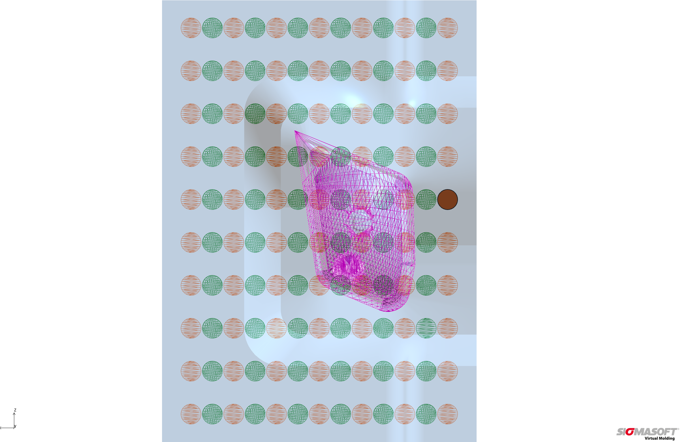
Therefore, first the ranges should be determined in which the heating cartridges have the largest influence on the cavity. On this basis, the optimum number and position is determined for each of these ranges. Among the uniformly distributed positions of all possible heating cartridges, the evaluation area in the mold – the cavity in which a uniform temperature of 150°C is to be achieved – is highlighted in pink (Fig. 2). In two computations (brown and green), the influence of each of 70 positions on the evaluation area is checked against a virtual DoE. The position is varied with reference to the center point of the cavity. To determine the influence of each position without the interference of the other cartridges, with each design there is only one heating cartridge taken into account for the whole mold at this specific position.
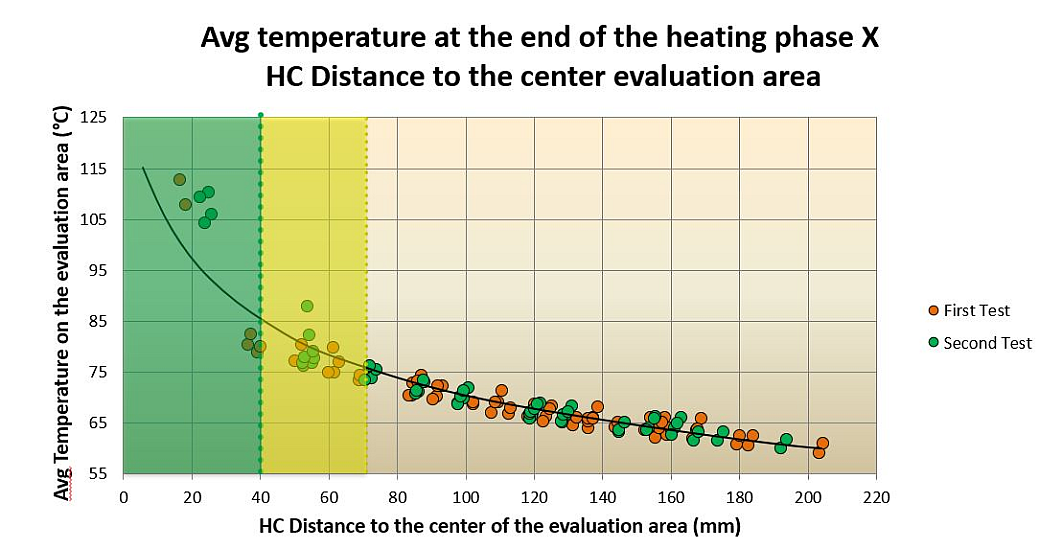
The influence of the heating cartridges on the cavity depends on the distance from the center point of the cavity (Fig. 3). For adequate heating, the regions with a radius of 40 mm (within the cavity) and 70 mm (immediately outside the cavity) around the center point are important. In the following calculations, the best position and number of heating cartridges for each of these regions is determined.
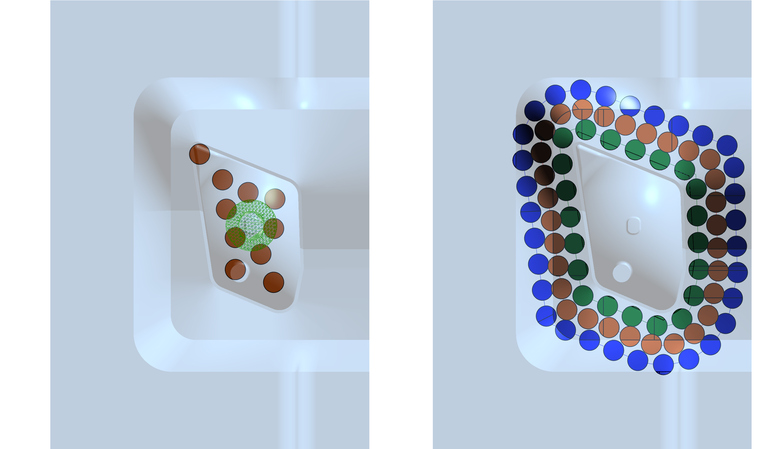
In the calculations, it quickly becomes clear that, in the interior region, four cartridges are adequate and further cartridges do not improve the result. A further virtual DoE is used for determining the cartridges outside the cavity (Fig. 4). Possible positions around the cavity at distances of 10mm (green), 25mm (brown) and 40mm (blue) are checked. The heating cartridges are uniformly distributed on the curves that are generated. For evaluation, it is assumed that the cavity is already heated to 150°C from the inside. The evaluation area for this calculation is therefore formed by a shell around the cavity core.
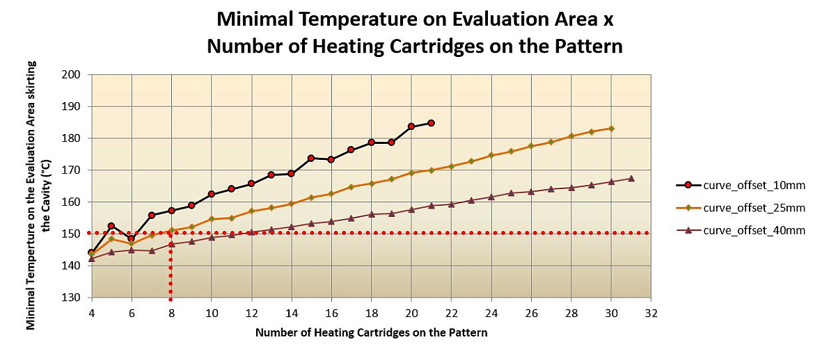
A graph (Fig. 5) shows the temperatures reached in the evaluation area, depending on the number and spacing of the cartridges. To allow a uniform distribution of the cartridges around the cavity and the subsequent heating zones, the configuration of eight cartridges is chosen at a distance of 25 mm for the mold concept.
Step 2: Position of the Control Points
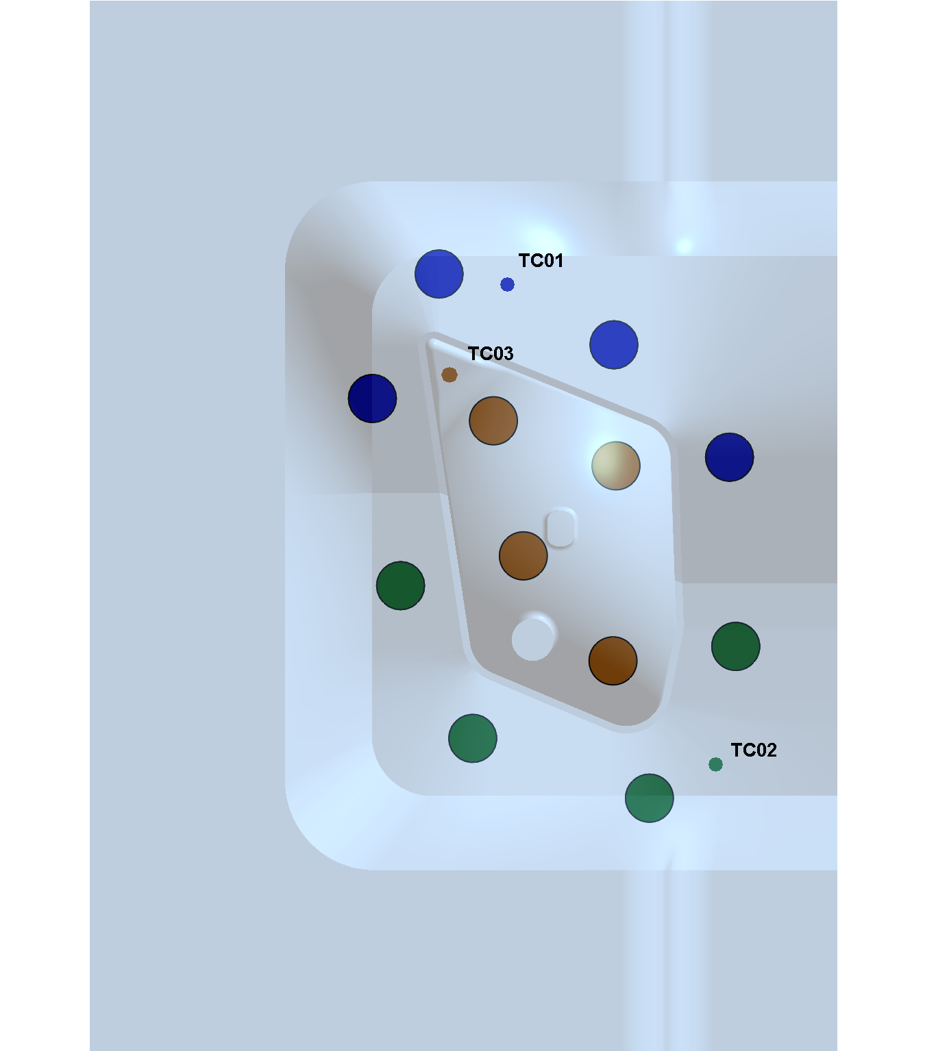
After the cartridges are arranged in a fixed constellation both within and outside the cavity, they are subdivided into heating zones. Corresponding to the boundary condition defined above, the required twelve cartridges are subdivided into three control circuits. The cartridges within the cavity are grouped into one circuit and the cartridges outside the cavity are divided so that each four adjacent cartridges are controlled from one control point (thermocouple = TC).
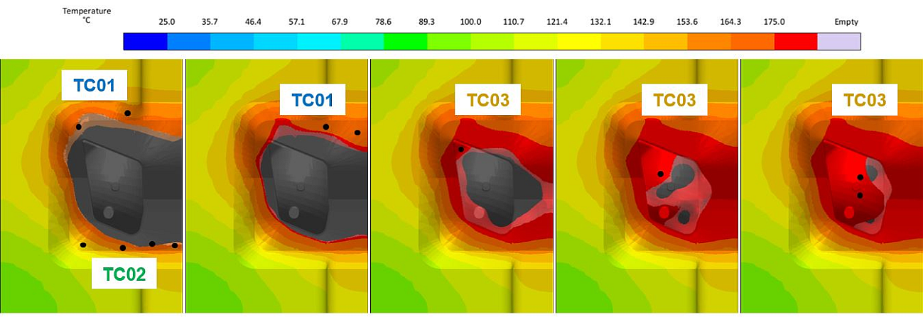
Since there is also an infinite number of ways of positioning these control points, the ideal positions for the control points are first limited via a thermal analysis of the mold with the planned configuration of the cartridges. For this, the mold is heated at maximum output throughout using the chosen cartridges. After a heating time of 30 min., those regions are determined which heat up slowest within each heating zone (Fig. 6). Within these regions four possible positions are determined for each control point.
These positions are subsequently checked in a further virtual DoE and compared. In contrast to previous computations, this is not done using continually heated cartridges, but with a conventional PI-controlled heater. Finally, the heating cartridges are subdivided into three heating circuits with the respective control points (TC) (Fig. 7).
Step 3: Robust Process and Necessary Heating Output
After the positions and numbers of the cartridges, as well as their optimum control points have been determined, it still remains to check whether, with this configuration, a robust process is also ensured at higher mold temperatures. At the same time, this final analysis can also be used to check whether the chosen heating performance (500 W) is necessary or whether the lower one (300 W) may even be sufficient.
For this purpose, mold temperatures of 150, 160 and 170°C are specified, and both the resulting temperature distribution and the respective utilization of the heating cartridges are assessed. The subsequent evaluation shows that the chosen configuration ensures a robust process even at higher mold temperatures. In addition, at the high temperatures, less than half of the possible heating output is called on in each control circuit. The mold could thus also operate with the heating cartridges having 300 W output.
Summary
Thanks to a structured procedure and a state-of-the-art approach to simulation, the optimum heating concept was determined for the BMC headlamp reflector. For three sub-problems, the best solution in each case was determined automatically with four virtual DoE with a total of 1304 variants. In this way, the original question with several million possible solutions could be answered by checking a fraction of the possible combinations. In total, all the necessary calculations are performed and evaluated in a few days, which corresponds to the time requirement of a conventional simulation-assisted trial-and-error approach.


