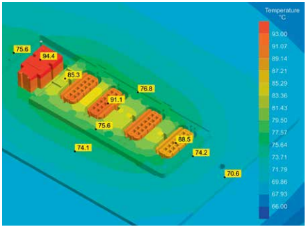
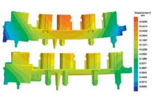
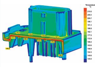
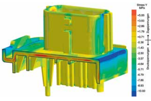
Ideally, optimization of the (uneven) volumetric shrinkage requires symmetric cooling conditions and/or a homogeneous temperature distribution. In the example described here, optimization of mold tempering, e.g. through conformal cooling, is not possible. Therefore, the only possibility to counteract the impeded heat flow in the upper component side consists of creating a higher temperature gradient within the mold.
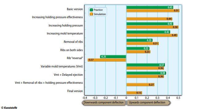
In practice, this means reducing the cooling medium temperature in this area, thereby removing more heat. The result is a 0.15 mm reduction of reflection in the simulation, and 0.08 mm in practice, accompanied by a drastic reduction of residual stresses, both before and after demolding. Analogously, volumetric shrinkage is very homogeneous, and exhibits a clearly lower value.
Rib Straightens the Component during Cooling
How large the frozen stresses finally are, and how strongly they act on the component, is demonstrated in the final unsuccessful attempt with delayed ejection. Hereby, and in order to prevent shrinkage on one side, the upper component side remains in the cavity on the ejector side for a certain time after the mold is opened. But the result of 0.36 mm (0.38 mm in practice) permits the conclusion that even before the mold is opened, the component already contains so many residual stresses that this measure has no effect.
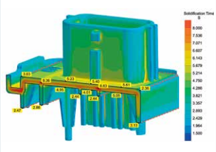
Worth mentioning, although not verified by practical tests, is the attempt to increase holding pressure effectiveness. In this case, and with the aim of supplying additional melt to all areas for as long as possible, flow promoters in the form of thick ribs were included on the (lower) component side, which solidifies earlier. However, the improvement of 0.07 mm is by no means due to an optimized supply of dwell pressure. In fact, it is shown that the rib cools down relatively slowly, thereby “pulling” the component straight after demolding. Remarkable: The same measure without the stiffening elements and with a variable mold temperature resulted in a deviation improvement of 0.12 mm (Fig. 7).
In conclusion, the study includes a final simulation, which combines several measures for optimizing deformation:
- increased holding pressure effectiveness,
- varying mold temperature, and
- removing ribs.
Although no practical test has been carried out for this combination of measures, the deflection of 0.15 mm achieved by the simulation indicates a clear improvement of component quality. Based on the positive results of the prior simulations, it is safe to assume that this version will also minimize distortion in practice.
Summary
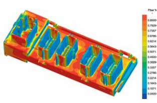
In all cases, in which the calculated component distortion can be verified by practical tests, the values coincide closely. Consequently, the quality of the simulation results is very high. Moreover, the software is able to demonstrate all three phenomena that are relevant for component distortion – thermal, geometrical, and anisotropically-induced distortion – thereby permitting targeted optimization measures.
Not least because of these positive results, /H&B/ Electronic has meanwhile established injection molding simulation as a permanent element of its development procedure. The first simulations to optimize the component’s design are carried out very early, followed by additional simulations during the further project stages and taking the mold design into account. In conclusion, a process simulation before the mold is commissioned forms the final quality check.

